Slide 1 of 19
Slide 1 - Logic Gates: Digital Foundations
Logic Gates: Digital Foundations
Understanding the Building Blocks of Modern Computing (Grade 10)
---
Photo by Logan Voss on Unsplash
Generated from prompt:
Create a professional and interactive presentation about "Logic Gates" for Grade 10 students. The presentation should: - Use a modern design with navy blue and white colors - Be visually engaging with icons, diagrams, and clean layout - Include simple explanations suitable for students Slides structure: 1. Title slide (Logic Gates) 2. Engaging question (about light switches) 3. Learning objectives 4. What is a logic gate? 5. Binary concept (0 and 1) 6. AND gate explanation with real-life example 7. AND truth table 8. OR gate explanation with real-life example 9. OR truth table 10. NOT gate explanation with real-life example 11. NOT truth table 12. Quick check questions 13. Activity: Complete the truth table 14. Activity: Match real-life scenarios 15. Challenge: Design a simple system using logic gates 16. Think-Pair-Share slide 17. Real-life applications 18. Summary 19. Exit ticket question 20. Closing slide Make the slides: - Clear and not crowded - Use bullet points only (no long paragraphs) - Add interactive elements like questions and activities - Use simple English suitable for students
This Grade 10 presentation explores logic gates as the building blocks of modern computing. It covers binary concepts, AND, OR, and NOT gates with truth tables, real-life examples, interactive activities, challenges, and applications in everyday tech
Logic Gates: Digital Foundations
Understanding the Building Blocks of Modern Computing (Grade 10)
---
Photo by Logan Voss on Unsplash
---
Photo by Drew Beamer on Unsplash
---
Photo by Drew Beamer on Unsplash
---
Photo by Drew Beamer on Unsplash
---
Photo by Drew Beamer on Unsplash
---
Photo by Drew Beamer on Unsplash
---
Photo by Drew Beamer on Unsplash
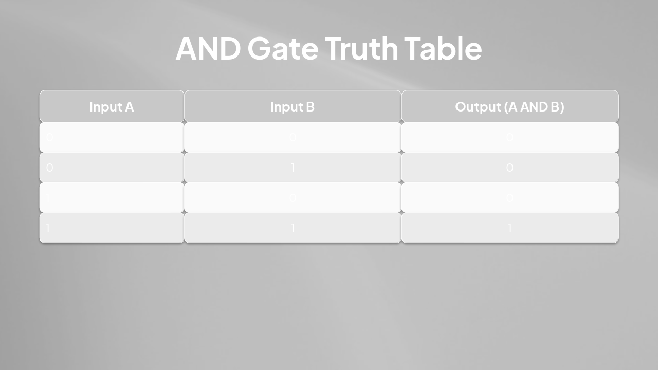
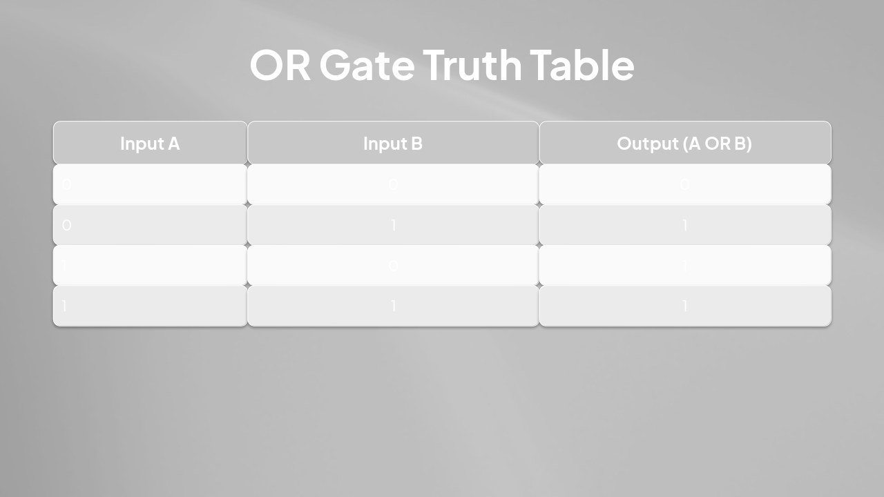
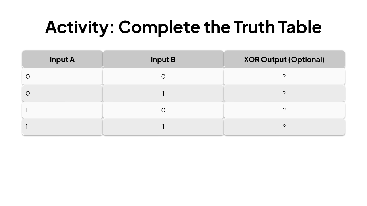
| Input A | Input B | Output (A OR B) |
|---|---|---|
| 0 | 0 | 0 |
| 0 | 1 | 1 |
| 1 | 0 | 1 |
| 1 | 1 | 1 |
---
Photo by Drew Beamer on Unsplash
---
Photo by Drew Beamer on Unsplash
---
Photo by Drew Beamer on Unsplash
---
Photo by Drew Beamer on Unsplash
---
Photo by Drew Beamer on Unsplash
---
Photo by Drew Beamer on Unsplash
---
Photo by Drew Beamer on Unsplash
---
Photo by Drew Beamer on Unsplash
---
Photo by Drew Beamer on Unsplash

Explore thousands of AI-generated presentations for inspiration
Generate professional presentations in seconds with Karaf's AI. Customize this presentation or start from scratch.