Slide 1 of 8
Slide 1 - Introduction to Structural Engineering
This title slide introduces the "CE470 – Structural Steel Design" course, focusing on the design of steel structures. It covers topics like structural members, connections, loads, and design methods, with the objective of understanding the systematic process of structural design.
Course focus: Design of steel structures
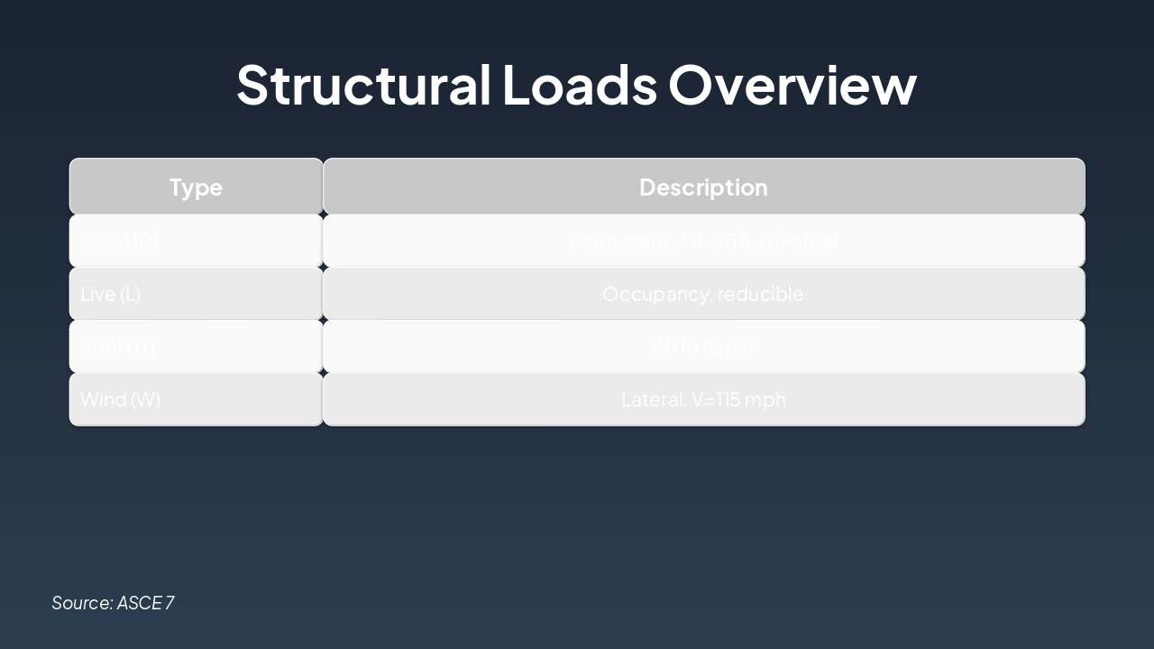
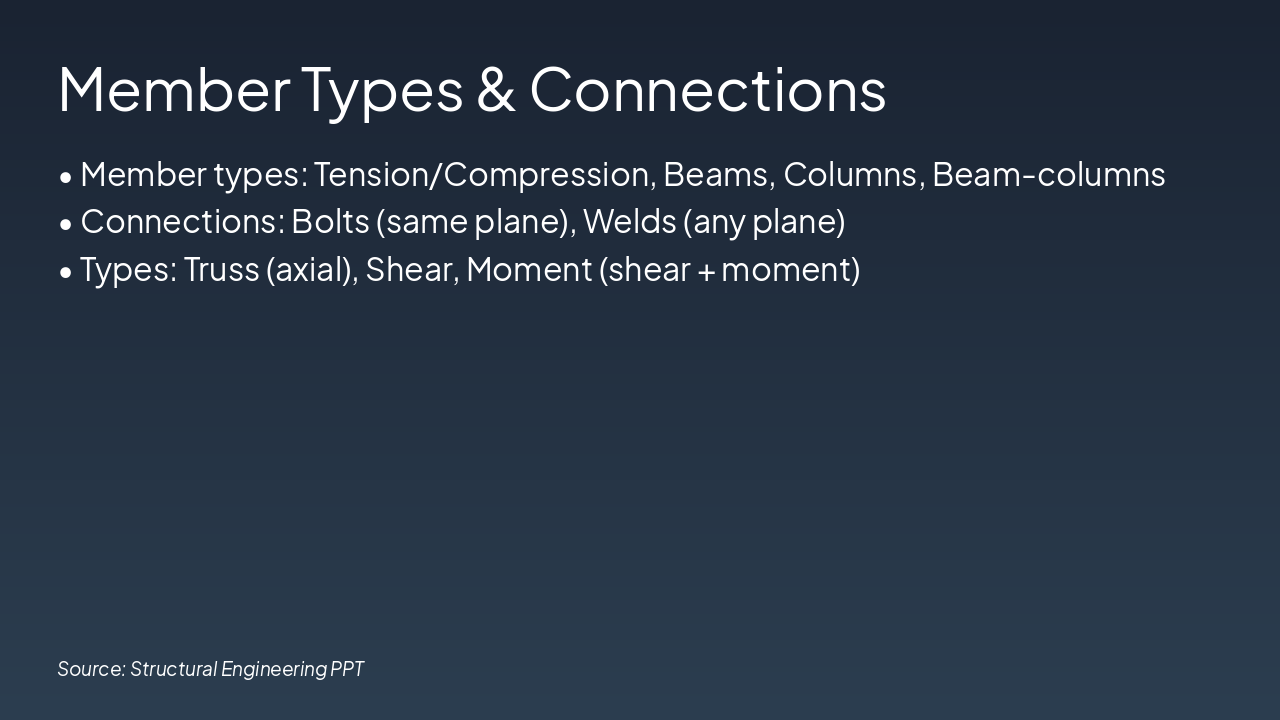
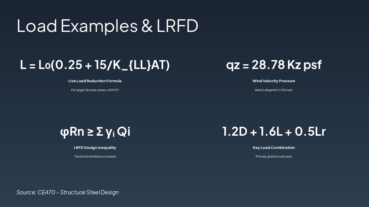
Topics: Structural members, connections, loads, and design methods
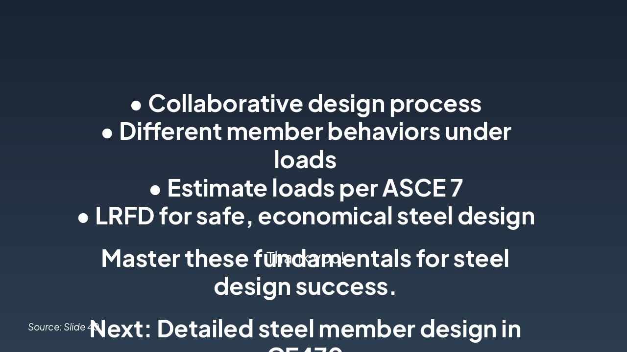
Objective: Understand the systematic process of structural design
CE470 – Structural Steel Design
Source: CE470 – Structural Steel Design