BJT Transistor Configurations: CE, CB, CC Fundamentals

Generated from prompt:

Create a college-level presentation on 'Transistor Configurations: Analyzing the Common Emitter (CE), Common Base (CB), and Common Collector (CC) circuits'. Include: - Title slide - Introduction to transistors (BJT basics) - Overview of configurations (CE, CB, CC) - Detailed slides for each configuration: circuit diagram, input/output characteristics, gain (current, voltage, power), phase relationship, input/output impedance, advantages, disadvantages, applications - Comparison table of CE vs CB vs CC - Graphs of characteristics - Real-world applications/examples - Conclusion - References Make it visually clean, suitable for engineering students, about 12-15 slides.

This presentation delves into Bipolar Junction Transistor (BJT) basics and the three key configurations: Common Emitter (CE), Common Base (CB), and Common Collector (CC). It covers characteristics, input/output impedances, phase shifts, comparative分析

April 23, 202615 slides
Slide 1 of 15

Slide 1 - Transistor Configurations

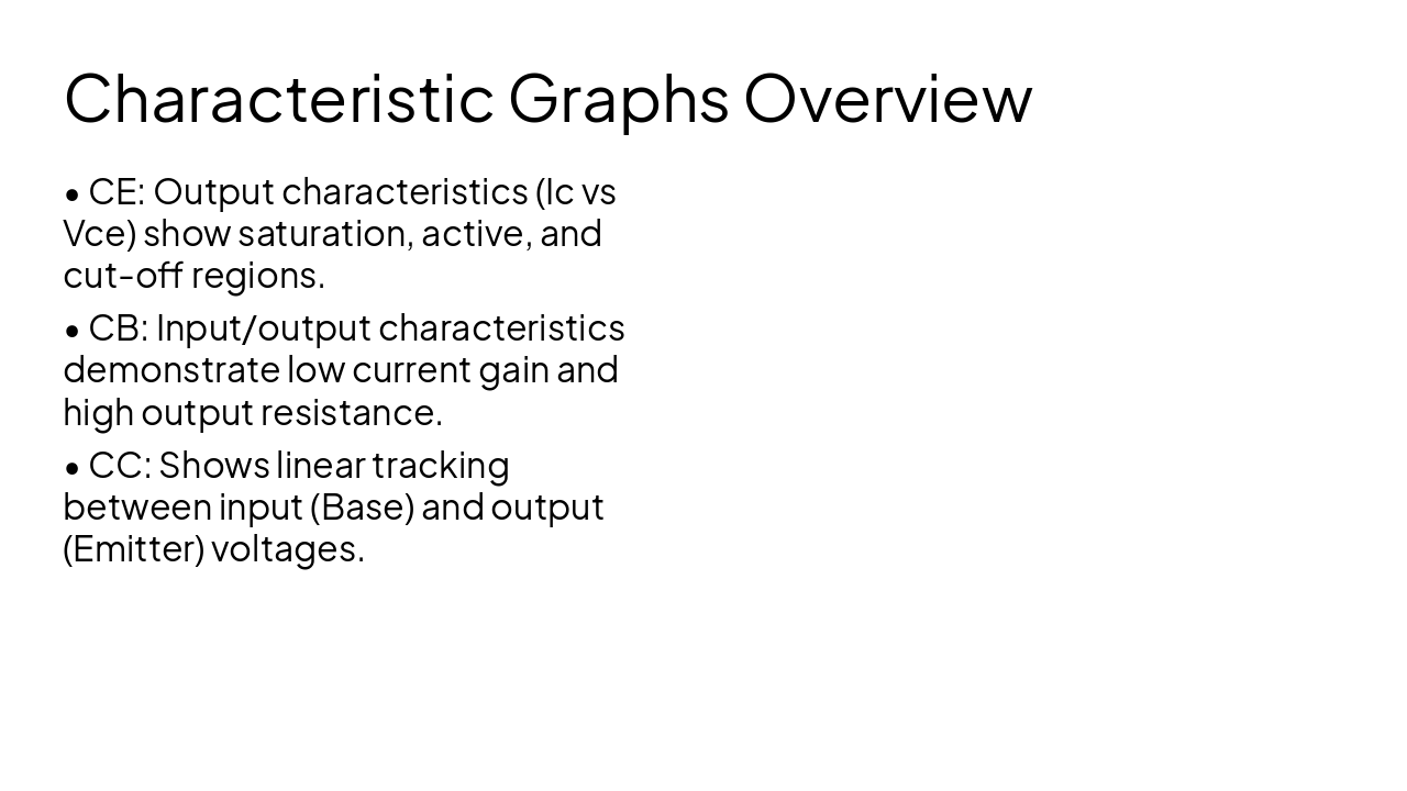
Transistor Configurations: BJT Fundamentals

Analyzing the Common Emitter, Common Base, and Common Collector Configurations

---

Photo by Igor Shalyminov on Unsplash

Slide 1 - Transistor Configurations
Slide 2 of 15

Slide 2 - Presentation Outline

  • Introduction to BJT Basics
  • Overview of Transistor Configurations
  • Common Emitter (CE) Configuration
  • Common Base (CB) Configuration
  • Common Collector (CC) Configuration
  • Comparative Analysis Summary
  • Applications and Conclusion

---

Photo by Randall Bruder on Unsplash

Slide 2 - Presentation Outline
Slide 3 of 15

Slide 3 - Introduction to BJT Basics

  • Bipolar Junction Transistor (BJT): A three-terminal device (Emitter, Base, Collector).
  • Operates as either an amplifier or a switch based on bias conditions.
  • Key mechanism: Small current at the Base terminal controls larger current between Collector and Emitter.
  • Modes of Operation: Active (Amplification), Cut-off (OFF), and Saturation (ON).
  • Key parameters: Beta (current gain) and Alpha (common-base current gain).
Slide 3 - Introduction to BJT Basics
Slide 4 of 15

Slide 4 - Overview of Configurations

  • The three configurations depend on which terminal is 'common' to both input and output circuits.
  • Common Emitter (CE): Emitter is common. Most widely used for voltage amplification.
  • Common Base (CB): Base is common. High frequency applications, low input impedance.
  • Common Collector (CC): Collector is common. Also known as Emitter Follower. High input impedance, used for impedance matching.
Slide 4 - Overview of Configurations
Slide 5 of 15

Slide 5 - Section Header

1

Common Emitter (CE) Configuration

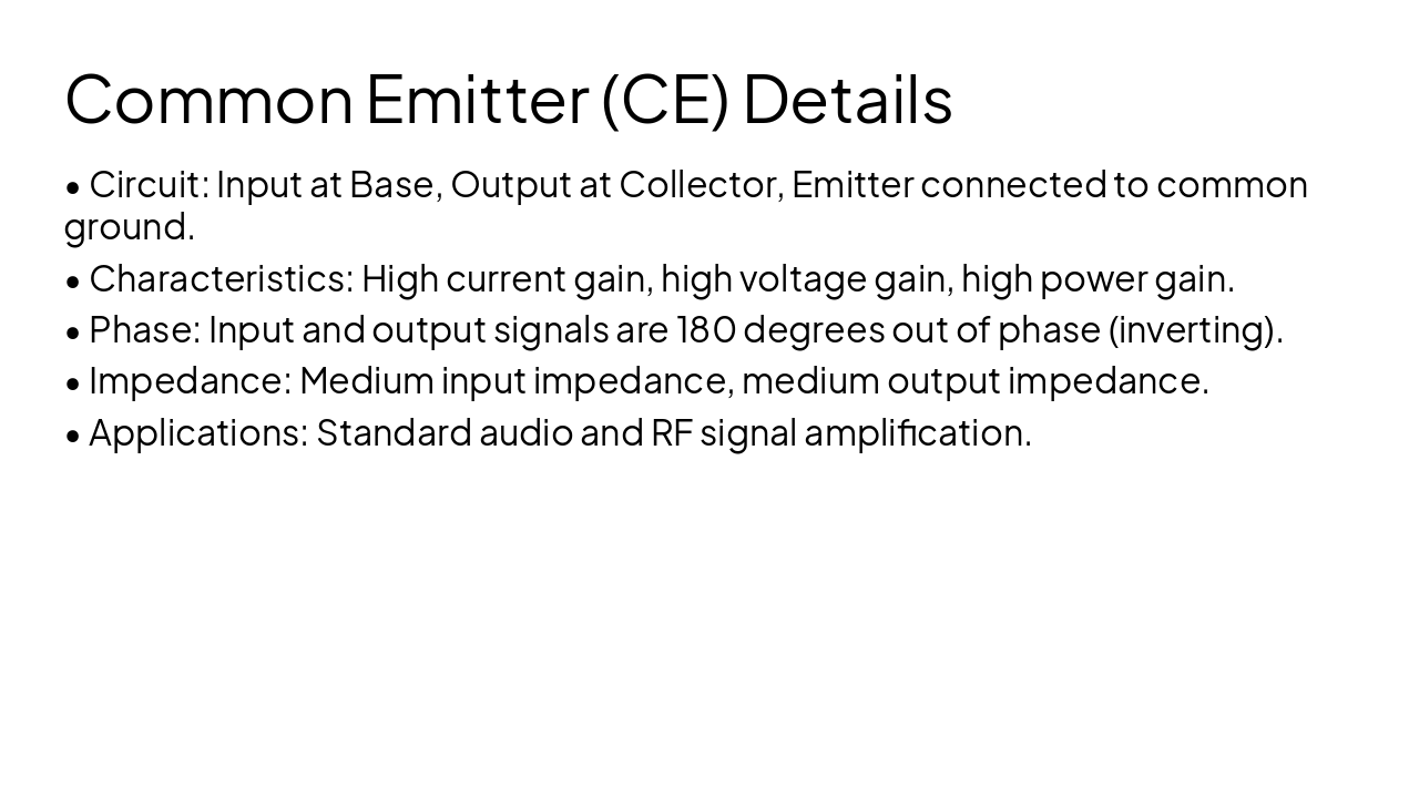
The fundamental amplifier circuit

Slide 5 - Section Header
Slide 6 of 15

Slide 6 - Common Emitter (CE) Details

  • Circuit: Input at Base, Output at Collector, Emitter connected to common ground.
  • Characteristics: High current gain, high voltage gain, high power gain.
  • Phase: Input and output signals are 180 degrees out of phase (inverting).
  • Impedance: Medium input impedance, medium output impedance.
  • Applications: Standard audio and RF signal amplification.
Slide 6 - Common Emitter (CE) Details
Slide 7 of 15

Slide 7 - Section Header

2

Common Base (CB) Configuration

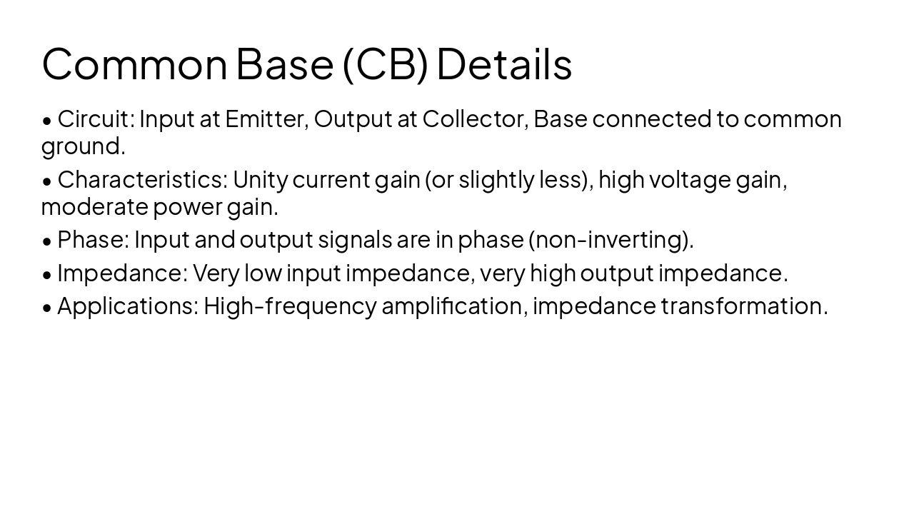
Optimized for high-frequency performance

---

Photo by Denny Müller on Unsplash

Slide 7 - Section Header
Slide 8 of 15

Slide 8 - Common Base (CB) Details

  • Circuit: Input at Emitter, Output at Collector, Base connected to common ground.
  • Characteristics: Unity current gain (or slightly less), high voltage gain, moderate power gain.
  • Phase: Input and output signals are in phase (non-inverting).
  • Impedance: Very low input impedance, very high output impedance.
  • Applications: High-frequency amplification, impedance transformation.
Slide 8 - Common Base (CB) Details
Slide 9 of 15

Slide 9 - Section Header

3

Common Collector (CC) Configuration

The Emitter Follower for buffering

---

Photo by Umberto on Unsplash

Slide 9 - Section Header
Slide 10 of 15

Slide 10 - Common Collector (CC) Details

  • Circuit: Input at Base, Output at Emitter, Collector connected to common supply (AC ground).
  • Characteristics: High current gain, unity voltage gain (slightly less than 1).
  • Phase: Input and output signals are in phase (non-inverting).
  • Impedance: Very high input impedance, very low output impedance.
  • Applications: Impedance matching, voltage buffers, driver circuits.
Slide 10 - Common Collector (CC) Details
Slide 11 of 15

Slide 11 - Comparison Table

ParameterCommon EmitterCommon BaseCommon Collector
Voltage GainHigh (100-1000)High (100-1000)Low (<1)
Current GainHigh (50-200)Low (<1)High (50-200)
Input ImpedanceMedium (~1k Ohm)Very Low (~20 Ohm)Very High (~100k Ohm)
Output ImpedanceMedium (~40k Ohm)Very High (>1M Ohm)Very Low (<100 Ohm)
Phase Shift180 degrees0 degrees0 degrees
Slide 11 - Comparison Table
Slide 12 of 15

Slide 12 - Characteristic Graphs Overview

  • CE: Output characteristics (Ic vs Vce) show saturation, active, and cut-off regions.
  • CB: Input/output characteristics demonstrate low current gain and high output resistance.
  • CC: Shows linear tracking between input (Base) and output (Emitter) voltages.
Slide 12 - Characteristic Graphs Overview
Slide 13 of 15

Slide 13 - Applications and Examples

  • Common Emitter: Audio pre-amplifiers, general-purpose switching circuits.
  • Common Base: High-frequency RF amplifiers (FM radio tuners), high-speed communication systems.
  • Common Collector: Audio output stages, impedance matching between high-impedance source and low-impedance load, voltage buffer circuits.
Slide 13 - Applications and Examples
Slide 14 of 15

Slide 14 - Conclusion

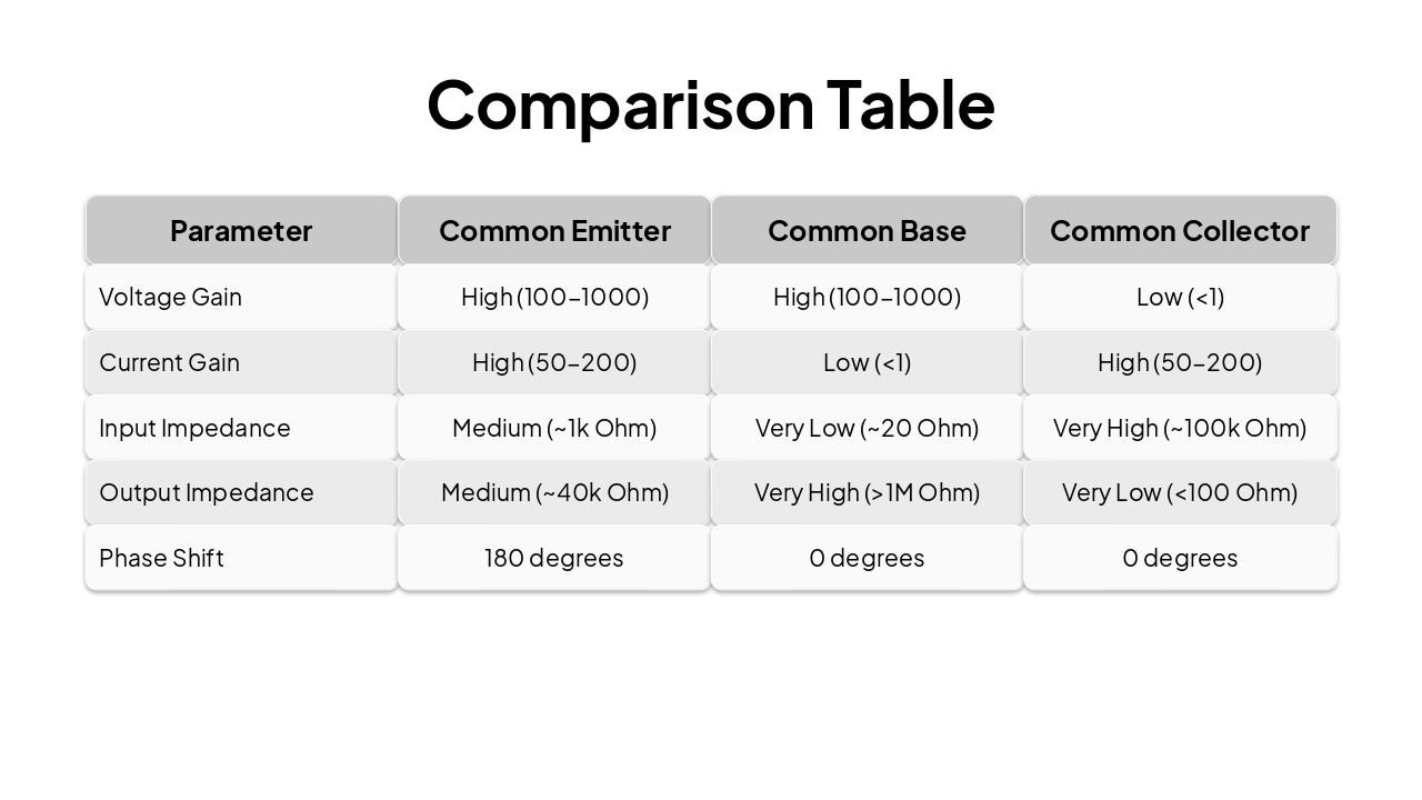
Understanding transistor configurations is critical for optimizing signal processing performance.

Summary of BJT configurations and their strategic use in electronic design.

---

Photo by Paul Brake on Unsplash

Slide 14 - Conclusion
Slide 15 of 15

Slide 15 - References

  • Millman, J., & Halkias, C. C. (1972). Integrated Electronics: Analog and Digital Circuits and Systems. McGraw-Hill.
  • Sedra, A. S., & Smith, K. C. (2004). Microelectronic Circuits (5th ed.). Oxford University Press.
  • Boylestad, R. L., & Nashelsky, L. (2009). Electronic Devices and Circuit Theory (10th ed.). Prentice Hall.
Slide 15 - References

Discover More Presentations

Explore thousands of AI-generated presentations for inspiration

Browse Presentations
Powered by AI

Create Your Own Presentation

Generate professional presentations in seconds with Karaf's AI. Customize this presentation or start from scratch.

Create New Presentation

Powered by Karaf.ai — AI-Powered Presentation Generator