Fiber Optics Fundamentals: TIR, Acceptance Angle & Numerical
Generated from prompt:
Create a professional 10-slide student presentation titled 'Optical Principles: Total Internal Reflection, Acceptance Angle, and Numerical Aperture'. Include clean academic design. Slide 1: Title Slide – Optical Principles with student name placeholder. Slide 2: Introduction to Fiber Optics and Light Propagation. Slide 3: Refraction and Snell’s Law (include simple ray diagram). Slide 4: Total Internal Reflection – Definition and Conditions (include labeled diagram). Slide 5: Critical Angle Formula and Explanation (include diagram showing critical angle). Slide 6: Applications of Total Internal Reflection in Optical Fibers (include fiber diagram). Slide 7: Acceptance Angle – Definition and Physical Meaning (include cone diagram). Slide 8: Numerical Aperture – Definition and Formula NA = n sin(theta) (include diagram). Slide 9: Relationship Between TIR, Acceptance Angle, and Numerical Aperture (summary diagram). Slide 10: Conclusion and Key Takeaways. Professional student formatting, minimal bullet points, academic style diagrams.
Student presentation on core optical principles for fiber optics: Total Internal Reflection (TIR) via Snell's Law and critical angle, acceptance angle defining light entry, Numerical Aperture (NA = √(n₁² - n₂²)), their interrelationships, and telecom


Slide 3 - Introduction to Fiber Optics and Light Propagation
- Optical fiber is a flexible glass or plastic fiber that transmits light from one end to the other.
- Widely used in fiber-optic communication for longer distances and higher bandwidths than electrical cables.
- Signals travel with less loss and are immune to electromagnetic interference.
- Core surrounded by cladding with lower refractive index; light kept in core by total internal reflection.
Source: Wikipedia: Optical fiber
Slide 4 - Refraction and Snell’s Law
- Refraction: Bending of light ray when entering a medium with different refractive index, due to change in light speed.
- Snell’s Law: n₁ sin θ₁ = n₂ sin θ₂ (n = refractive index, θ = angle of incidence/refraction from normal).
- Predicts path of light ray; essential for TIR in optical fibers.
Slide 5 - Total Internal Reflection – Definition and Conditions
- Definition: Complete reflection of light at boundary from denser (higher n) to rarer (lower n) medium.
- Conditions: Light from n₁ > n₂, angle of incidence θi > critical angle θc.
- No light transmitted into second medium; acts as perfect mirror.
- Enables light guiding in optical fibers.
---
Photo by Hassaan Here on Unsplash
Source: Wikipedia: Optical fiber
Slide 6 - Critical Angle Formula and Explanation
- Critical Angle θc: Angle of incidence where angle of refraction is 90° (along boundary).
- Formula: sin θc = n₂ / n₁, where n₁ (core) > n₂ (cladding).
- For θi < θc: Partial reflection and refraction.
- For θi = θc: Refraction at 90°.
- For θi > θc: Total Internal Reflection.
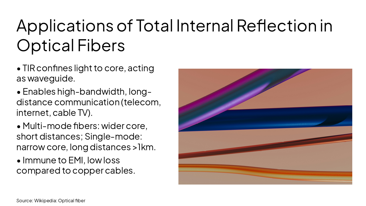
Slide 7 - Applications of Total Internal Reflection in Optical Fibers
- TIR confines light to core, acting as waveguide.
- Enables high-bandwidth, long-distance communication (telecom, internet, cable TV).
- Multi-mode fibers: wider core, short distances; Single-mode: narrow core, long distances >1km.
- Immune to EMI, low loss compared to copper cables.
---
Photo by Steve Johnson on Unsplash
Source: Wikipedia: Optical fiber
Slide 8 - Acceptance Angle – Definition and Physical Meaning
- Acceptance Angle (θa): Maximum angle relative to fiber axis for incident light to be guided by TIR.
- Light rays steeper than θa will not satisfy TIR condition inside fiber.
- Physical meaning: Defines 'light-gathering' capability of fiber.
- Visualized as a cone at fiber input end.
Slide 9 - Numerical Aperture – Definition and Formula
- Numerical Aperture (NA): Figure of merit for light acceptance ability of fiber.
- Formula: NA = n₀ sin θa ≈ sin θa (in air, n₀=1), where θa = acceptance angle.
- Also: NA = √(ncore² - nclad²).
- Higher NA → larger acceptance cone, more light coupled into fiber.
---
Photo by MARIOLA GROBELSKA on Unsplash
Slide 10 - Relationship Between TIR, Acceptance Angle, and Numerical Aperture
- TIR requires internal incidence > θc = arcsin(n₂/n₁).
- Max internal angle relates to entrance acceptance angle θa via Snell’s law.
- NA = sin θa = √(n₁² - n₂²) links all parameters.
- Core principle enabling efficient light guidance in fibers.
---
Photo by MARIOLA GROBELSKA on Unsplash
Slide 11 - Conclusion and Key Takeaways
TIR enables light guiding in fibers Acceptance Angle defines light entry NA = √(n₁² - n₂²) quantifies efficiency
Essential principles for modern fiber-optic communications Thank you! Questions?
Discover More Presentations
Explore thousands of AI-generated presentations for inspiration
Create Your Own Presentation
Generate professional presentations in seconds with Karaf's AI. Customize this presentation or start from scratch.