Comprehensive Guide to Car Fault Detectors: Components, Theory of Operation, and Diagrams

Generated from prompt:

Report on the explanation, clarification, components and theory of the work of the car fault detector in detail and drawing

This presentation delivers a thorough examination of car fault detectors used in automotive diagnostics. It covers the introduction to On-Board Diagnostics (OBD) systems, key hardware and software components, essential vehicle sensors and ECUs, the core theory of fault detection, detailed workflows, system diagrams, common fault statistics, and key takeaways for effective vehicle repair and maintenance.

May 6, 202615 slides
Slide 1 of 15

Slide 1 - Explanation, Components, Theory of Operation and Diagrams

Explanation, Components, Theory of Operation and Diagrams

Comprehensive Report on Automotive Diagnostic Systems

---

Photo by Kevin Schmid on Unsplash
Slide 1 - Explanation, Components,
Theory of Operation
and Diagrams
Slide 2 of 15

Slide 2 - Agenda

  • Introduction to Car Fault Detectors
  • Key Components (Hardware & Software)
  • Sensors and ECUs in Vehicles
  • Theory of Operation
  • Fault Detection Workflow
  • Detailed Diagrams
  • Conclusion and Key Takeaways

---

Photo by Jasper on Unsplash

Slide 2 - Agenda
Slide 3 of 15

Slide 3 - Section 1: Introduction

1

Introduction

What is a Car Fault Detector and Why It Matters

---

Photo by Arteum.ro on Unsplash

Slide 3 - Section 1: Introduction
Slide 4 of 15

Slide 4 - What is a Car Fault Detector?

  • Device that interfaces with vehicle's On-Board Diagnostics (OBD) system
  • Reads Diagnostic Trouble Codes (DTCs) stored by Engine Control Unit (ECU)
  • Identifies faults in engine, transmission, emissions, and other systems
  • Common types: OBD-II scanners, code readers, professional diagnostic tools
  • Mandatory in most vehicles post-1996 (US) / 2001 (EU) for emissions compliance
  • Provides real-time data, freeze frame info, and readiness monitors
Slide 4 - What is a Car Fault Detector?
Slide 5 of 15

Slide 5 - Section 2: Components

2

Components

Hardware, Software, and Vehicle-Side Elements

---

Photo by James Lewis on Unsplash
Slide 5 - Section 2: Components
Slide 6 of 15

Slide 6 - Hardware Components of Fault Detector

  • OBD-II Connector (16-pin J1962 standard)
  • Microcontroller Unit (MCU) for protocol handling
  • Display/LCD screen or Bluetooth module for output
  • Power supply (from vehicle 12V)
  • LED indicators for status
  • Optional: SD card slot for data logging
Slide 6 - Hardware Components of Fault Detector
Slide 7 of 15

Slide 7 - Software Components

  • Protocol interpreters (ISO 9141, KWP2000, CAN, etc.)
  • DTC database and descriptions
  • User interface software
  • Data logging and export functions
  • Real-time graphing for live data
  • Bidirectional controls (advanced tools)
Slide 7 - Software Components
Slide 8 of 15

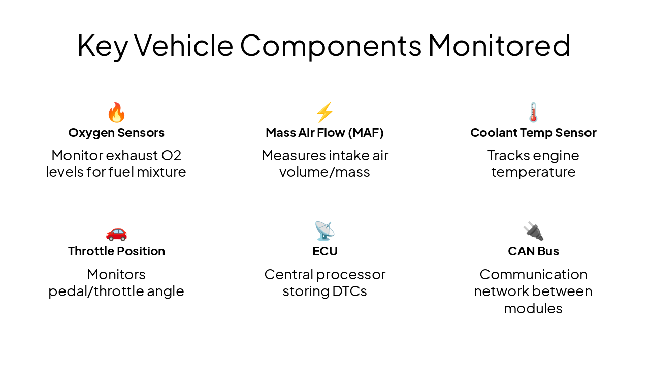
Slide 8 - Key Vehicle Components Monitored

🔥 Oxygen Sensors Monitor exhaust O2 levels for fuel mixture

Mass Air Flow (MAF) Measures intake air volume/mass

🌡️ Coolant Temp Sensor Tracks engine temperature

🚗 Throttle Position Monitors pedal/throttle angle

📡 ECU Central processor storing DTCs

🔌 CAN Bus Communication network between modules
Slide 8 - Key Vehicle Components Monitored
Slide 9 of 15

Slide 9 - Section 3: Theory of Operation

3

Theory of Operation

Principles Behind Fault Detection

---

Photo by Randall Bruder on Unsplash
Slide 9 - Section 3: Theory of Operation
Slide 10 of 15

Slide 10 - Core Theory

  • Sensors continuously monitor parameters (temp, pressure, RPM, etc.)
  • ECU compares readings against predefined thresholds and rationality checks
  • If out-of-range or implausible, ECU sets DTC (e.g., P0300 - Random Misfire)
  • DTC includes code, description, freeze-frame data (conditions at fault)
  • MIL (Check Engine Light) illuminates after 2-3 drive cycles
  • Scanner requests PID (Parameter IDs) via protocols like CAN (ISO 15765)
Slide 10 - Core Theory
Slide 11 of 15

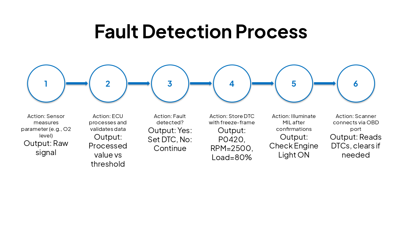
Slide 11 - Fault Detection Process

StepActionOutput
1Sensor measures parameter (e.g., O2 level)Raw signal
2ECU processes and validates dataProcessed value vs threshold
3Fault detected?Yes: Set DTC, No: Continue
4Store DTC with freeze-frameP0420, RPM=2500, Load=80%
5Illuminate MIL after confirmationsCheck Engine Light ON
6Scanner connects via OBD portReads DTCs, clears if needed
Slide 11 - Fault Detection Process
Slide 12 of 15

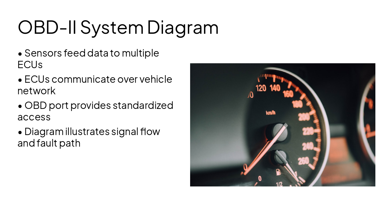
Slide 12 - OBD-II System Diagram

  • Sensors feed data to multiple ECUs
  • ECUs communicate over vehicle network
  • OBD port provides standardized access
  • Diagram illustrates signal flow and fault path

---

Photo by CHUTTERSNAP on Unsplash

Slide 12 - OBD-II System Diagram
Slide 13 of 15

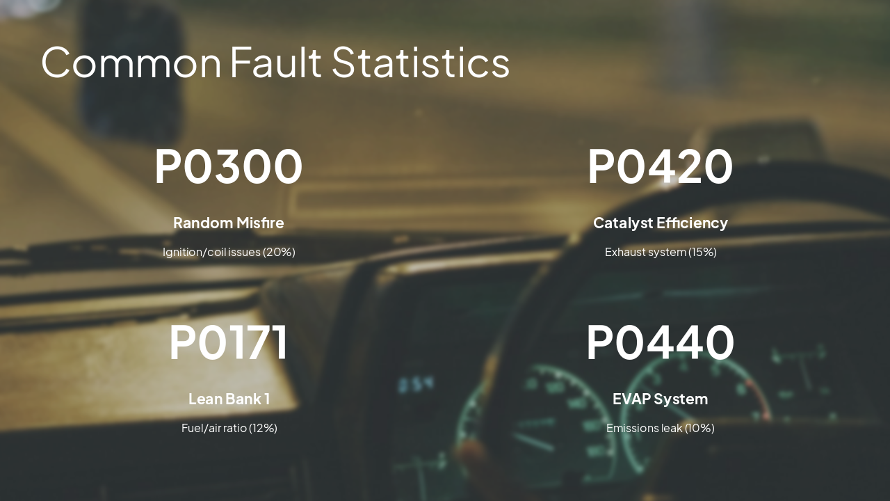
Slide 13 - Common Fault Statistics

  • P0300: Random Misfire
  • P0420: Catalyst Efficiency
  • P0171: Lean Bank 1
  • P0440: EVAP System

---

Photo by Jasper on Unsplash

Slide 13 - Common Fault Statistics
Slide 14 of 15

Slide 14 - Car ECU and Sensor Layout

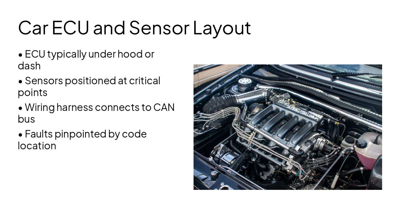
  • ECU typically under hood or dash
  • Sensors positioned at critical points
  • Wiring harness connects to CAN bus
  • Faults pinpointed by code location

---

Photo by Luca Hooijer on Unsplash
Slide 14 - Car ECU and Sensor Layout
Slide 15 of 15

Slide 15 - Conclusion

Mastering car fault detectors involves understanding OBD protocols, ECU logic, and sensor networks. Essential for modern vehicle diagnostics and repair.

Thank you! Questions?

---

Photo by Bangun Stock Production on Unsplash
Slide 15 - Conclusion

Discover More Presentations

Explore thousands of AI-generated presentations for inspiration

Browse Presentations
Powered by AI

Create Your Own Presentation

Generate professional presentations in seconds with Karaf's AI. Customize this presentation or start from scratch.

Create New Presentation

Powered by Karaf.ai — AI-Powered Presentation Generator